In formal spatial models, we need a way of defining relationships between observations. In the spatial analysis and econometrics literature, the data structure used to relate observations to one another is canonically called a spatial weights matrix, or \(W\), and is used to specify the hypothesized interaction structure that may exist between spatial units (Getis, 2009). These relationships between units form a special kind of network graph embedded in geographical space, and using the libpysal.graph module, we can explore these relationships in depth.
Code
%load_ext jupyter_black%load_ext watermark%watermark -v -a "author: eli knaap"-d -u -p libpysal
Author: author: eli knaap
Last updated: 2025-11-23
Python implementation: CPython
Python version : 3.12.12
IPython version : 9.7.0
libpysal: 4.13.0
Note
The Graph class is only available in versions of libpysal >=4.9. With versions prior to that, you need to use the W class, which works a little differently than demonstrated here.
Code
import contextily as ctximport matplotlib.pyplot as pltimport pandas as pdimport geopandas as gpdimport networkx as nximport osmnx as oximport pandarm as pdnafrom geosnap import DataStorefrom geosnap import io as giofrom libpysal.graph import Graphdatasets = DataStore()
OMP: Info #276: omp_set_nested routine deprecated, please use omp_set_max_active_levels instead.
The graph will use the geodataframe index to identify unique observations, so when we have something meaningful (like a FIPS code) that serves as an “id variable”, then we should set that as the index.
Code
dc = gio.get_acs(datasets, state_fips="11", years=2021)dc = dc.to_crs(dc.estimate_utm_crs())dc = dc.set_index("geoid")dc.plot()plt.show()
/Users/knaaptime/miniforge3/envs/urban_analysis/lib/python3.12/site-packages/geosnap/io/util.py:273: UserWarning: Unable to find local adjustment year for 2021. Attempting from online data
warn(
/Users/knaaptime/miniforge3/envs/urban_analysis/lib/python3.12/site-packages/geosnap/io/constructors.py:218: UserWarning: Currency columns unavailable at this resolution; not adjusting for inflation
warn(
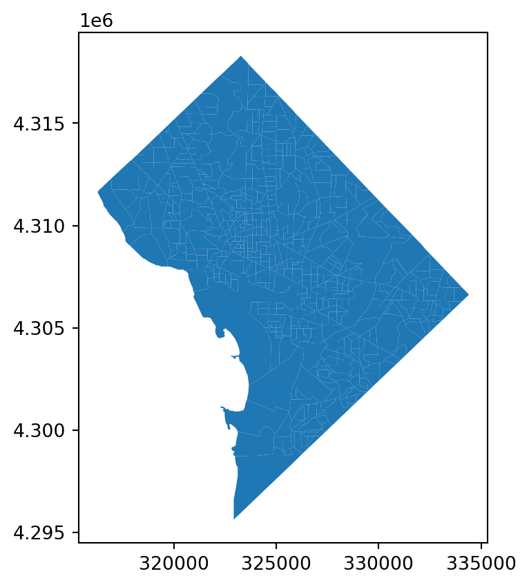
Blockgroups in Washington D.C.
The most common way of creating a spatial interaction graph is by “building” one from an existing geodataframe. The libpysal.graph.Graph class has a several methods available to generate these relationships, all of which use the Graph.build_* convention.
7.1 Contiguity Graphs
A contiguity graph assumes observations have a relationship when they share an edge and/or vertex. These are conceptually simple relationships that make sense for polygon-based data, and they encode “neighborhoods” when observations share sides (edges), corners (nodes), or a combination of the two. When observation data are encoded as points, it’s technically possible to use contiguity relationships if we rely on certain assumptions, however, strictly speaking it’s not possible for points to be be contiguous with one another.
Since many datasets in urban studies are based on polygons (e.g. administrative units), and a great deal of early research in spatial analysis was based on polygon lattice data (think counties in the U.S.), contiguity relationships are one of the most common forms of spatial Graphs used in practice.
Note
To use “contiguity” relationships using point-based observation data, it is common to use a Vornoi tesselation, which results in a set of implied polygons that encode each point (based on creating equidistance boundaries). When point data are used to create contiguity Graphs, libpysal uses this technique under the hood.
7.1.1 Rook
Code
g_rook = Graph.build_contiguity(dc)g_rook.n
571
The number of observations in our graph (the .n attribute) should match the number of rows in the dataframe from which it was constructed.
Code
dc.shape[0]
571
One way to interact with the graph structure directly is to use the adjacency attribute which returns the neighbor relationships as a multi-indexed pandas series.
“Slicing” into a Graph object returns a pandas series where the index is the neighbor’s id/key and the value is the “spatial weight” that encodes the strength of the connection between observations.
The cardinalities attribute stores the number of connections/relationships for each observation. In graph terminology, that would be the number of edges for each node, and in simple terms, this is the number of neighbors for each unit of analysis
count 571.000000
mean 5.162872
std 1.919363
min 2.000000
25% 4.000000
50% 5.000000
75% 6.000000
max 30.000000
Name: cardinalities, dtype: float64
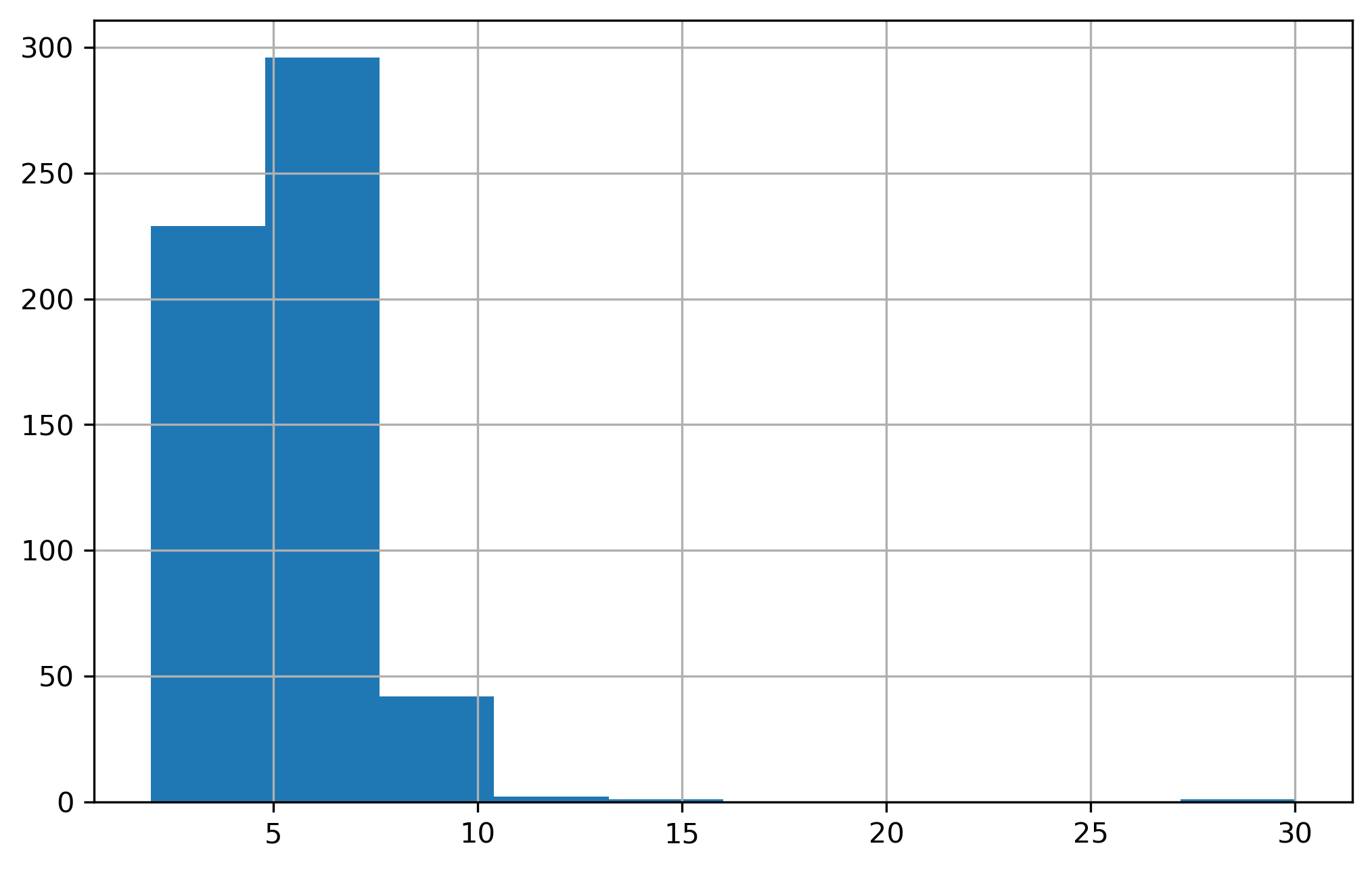
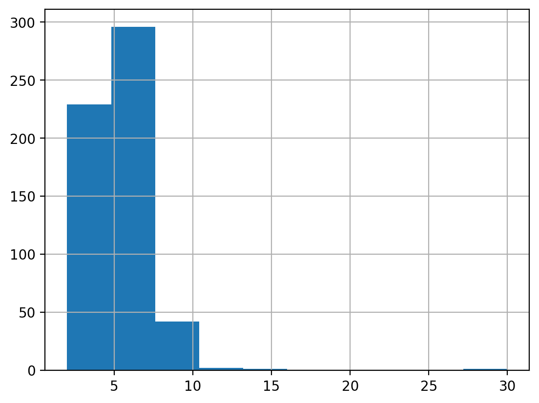
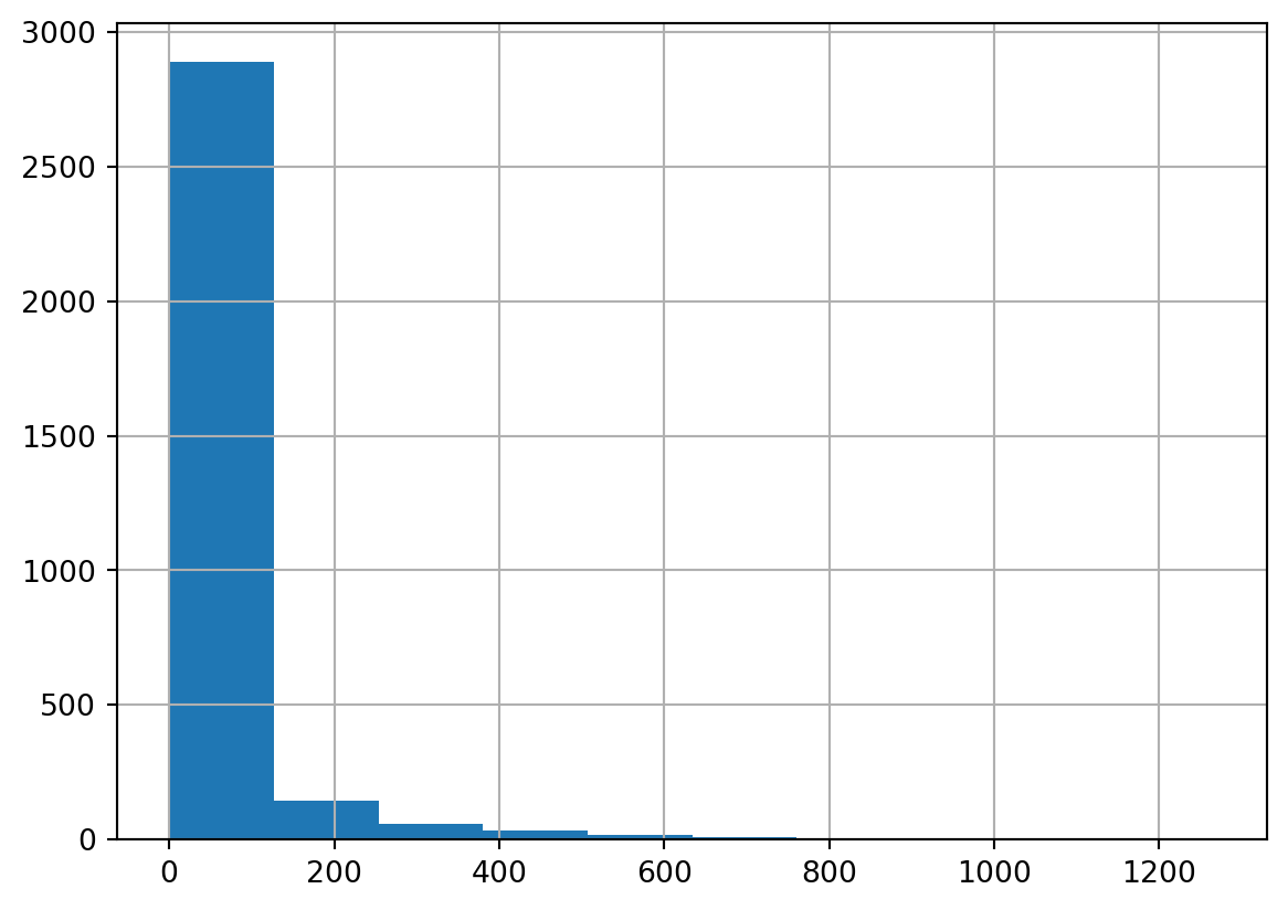
We can get a sense for what the neighbor distribution looks like by plotting a histogram of the cardinalities
Code
g_rook.cardinalities.hist()plt.show()
Histogram of Rook Graph Cardinalities
The attribute pct_nonzero stores the share of entries in the \(n \times n\) connectivity matrix that are non-zero. If every observation were connected to every other observation, this attribute would equal 1
Code
g_rook.pct_nonzero
0.9041807625421343
In this graph, less than 1% of the entries in that matrix are non-zero, showing that this is a very sparse connectivity graph indeed. Note, to compute the pct_nonzero measure ourselves, we could alternatively rely on properties of the graph:
Code
(g_rook.n_edges / g_rook.n_nodes**2) *100
0.9041807625421342
To see the full \(n \times n\) matrix representation of the graph, the sparse (scipy) representation is available under the sparse attribute
Code
g_rook.sparse
<Compressed Sparse Row sparse array of dtype 'float64'
with 2948 stored elements and shape (571, 571)>
To see the dense version, just convert from sparse to dense using scipy conventions. Both rows and columns of the matrix representation are ordered as found in the geodataframe from which the Graph was constructed (or in the order given, when using a _from_* method). Currently this order is stored under the unique_ids attribute.
Classic spatial connectivity graphs are typically very sparse. That is, we generally do not consider every observation to have a relationship with every other observation. Rather, we tend to encode relationships such that observations are influenced directly by other observations that are nearby in physical space. But because nearby observations also interact with their neighbors, it is possible for an influence from one observation to influence another observation far away by traversing the graph.
One useful way to understand how the Graph encodes spatial relationships is to use the plot method, which embeds the graph in planar space showing how observations are connected to one another. In the default plot, each observation (or its centroid, if the observations are polygons) is shown as a dot (or node in graph terminology), and a line (or edge) is drawn between nodes that are connected. Since we are using a rook contiguity rule, the edge, here, indicates that the observations share a common border.
Make this Notebook Trusted to load map: File -> Trust Notebook
Code
mall = gpd.overlay(cap, dc.reset_index())
Using an overlay operation from geopandas, we can collect the geoid we need to select from the Graph. For each observation in cap, the overlay will return the observations from dc that meet the spatial predicate (the default is intersect). (we reset the index here because we need to get the ‘geoid’ from the dataframe)
Code
mall
address
geoid
n_total_housing_units
n_vacant_housing_units
n_occupied_housing_units
n_owner_occupied_housing_units
n_renter_occupied_housing_units
n_housing_units_multiunit_structures_denom
n_housing_units_multiunit_structures
n_total_housing_units_sample
...
p_hispanic_persons
p_native_persons
p_asian_persons
p_hawaiian_persons
p_asian_indian_persons
p_edu_hs_less
p_edu_college_greater
p_veterans
year
geometry
0
U.S. National Archives, 700, Pennsylvania Aven...
110019800001
5.0
0.0
5.0
0.0
5.0
5.0
5.0
5.0
...
0.0
0.0
0.0
0.0
0.0
0.0
100.0
0.0
2021
POINT (324559.841 4306818.589)
1 rows × 59 columns
Code
mall_id = mall.geoid.tolist()[0]
Code
mall_id
'110019800001'
Since the graph encodes the notion of a “neighborhood” for each unit, it can be a useful way of selecting (and visualizing) “neighborhoods” around a particular observation. For example here are all the blockgroups that neighbor the National Mall national gallery of art (well, the blockgroup that contains the national gallery of art)
Warning
The resulting point from the codeblocks above depends on which geocoder is applied and also which version of the geodocoder is applied. In early drafts of this book, point often fell on the National Gallery of Art, however when the code is run more recently, the point sometimes falls elsewhere (fortunately, it always falls in the same–very large–census tract in my experience). When you use a geocoder, it’s important to remember the qualirt of the result is always based on the underlying data and is subject to change over time
Code
m = dc.loc[[mall_id]].explore(color="red", tooltip=None, tiles="CartoDB Positron")dc.loc[g_rook[mall_id].index].explore(m=m, tooltip=None)
Make this Notebook Trusted to load map: File -> Trust Notebook
Since blockgroups vary in size, and the national mall is in an oddly shaped blockgroup, its neighbor set includes blockgroups from Georgetown (Northwest), to Capitol Hill (Northeast), to Anacostia (Southeast)…
When plotting the graph, it is also possible to select subsets and/or style nodes and edges differently. Here we can contrast the neighborhood structure for the blockgroup containing the national mall versus another blockgroup near rock creek park. Passing those two indices (in a list) to the focal argument will plot only the subgraph for those two nodes.
Make this Notebook Trusted to load map: File -> Trust Notebook
Since the relationship graph is just a specific kind of network, we can also export directly to NetworkX, e.g. to leverage other graph theoretic measures. For example we could compute the degree of each node in the network and plot its distribution
Code
nxg = g_rook.to_networkx()pd.Series([i[1] for i in nxg.degree()]).hist()
Histogram of Degree Centrality for Rook Graph
And here it is easy to see that the degree of each node is the number of neighbors (which is the same as the cardinalities attribute of the original libpysal graph)
7.1.2 Queen
Code
g_queen = Graph.build_contiguity(dc, rook=False)
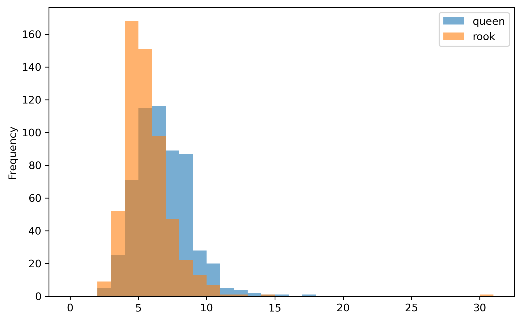
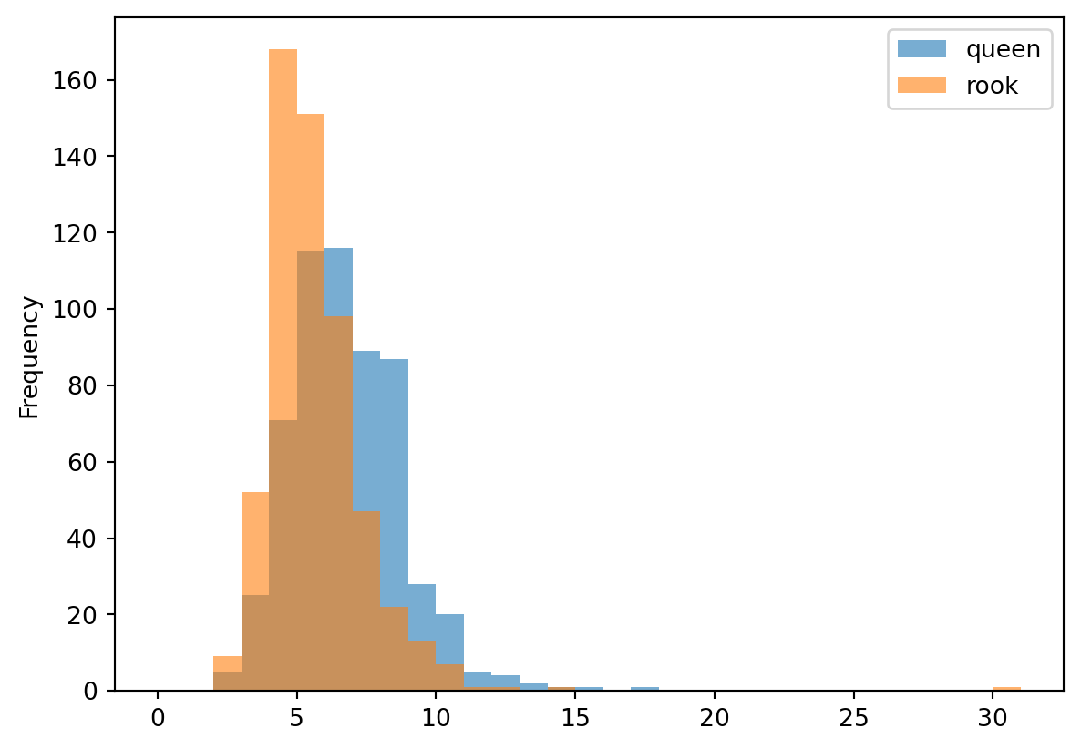
Since the ‘queen’ rule is more liberal and allows connections through the vertices as well as the edges, we would expect that each observation would have more neighbors, shifting our cardinality histogram to the right, and densifying the graph.
Code
g_queen.pct_nonzero
1.1096763903926192
Code
g_rook.pct_nonzero
0.9041807625421343
This fact is easy to verify using attributes of each Graph object; the Rook graph has a higher share of non-zero elements than the Queen graph. We can also see this visually by plotting both Graphs. In the plots, the neighbor density is visualized by the greater number of lines connecting each observation. That is, the Queen graph appears denser because there are more lines connecting the tracts.
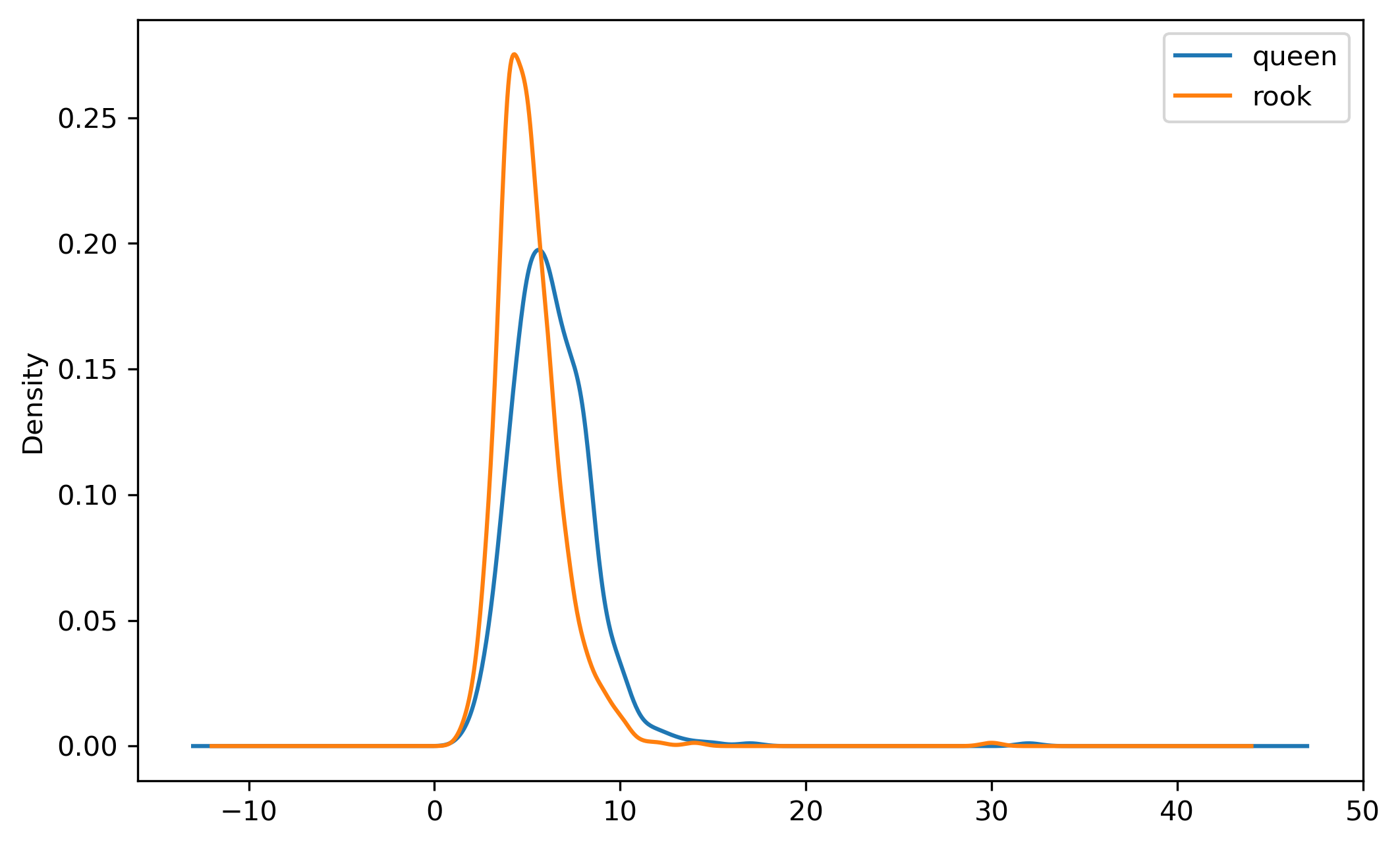
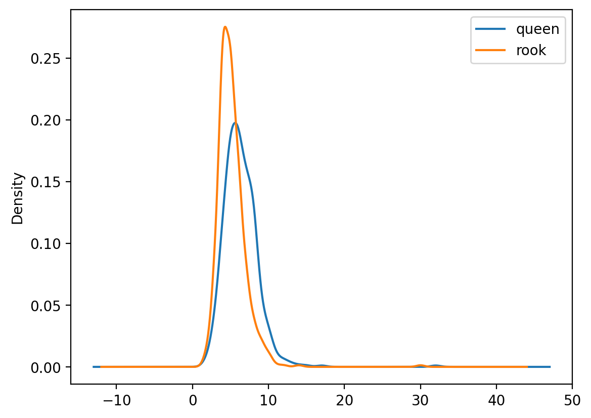
Plotting a kernel density estimate of the cardinalities of both graphs is another way to verify the difference between neighbor densities. In this case, we can see that the distribution for the Queen graph is shifted slightly to the right, indicating that, on average, Queen observations have more neighbors (which is another way of saying denser relationships).
Ultimately, though, the structure of the graph has not changed that substantially. If we plot both figures and scrutinize them side-by-side, a handful of differences emerge, but not many.
The Queen graph subsumes the Rook graph, so if we plot the queen relationships beneath the rook relationships in a different color, then the colors still visible underneath show the difference between queen and rook graphs.
Anything visible in blue is a connection through a vertex. But there is also a better way to do this…
7.1.3 Bishop Weights
In theory, a “Bishop” weighting scheme is one that arises when only polygons that share vertexes are considered to be neighboring. But, since Queen contiguigy requires either an edge or a vertex and Rook contiguity requires only shared edges, the following relationship is true:
\[ \mathcal{Q} = \mathcal{R} \cup \mathcal{B} \]
where \(\mathcal{Q}\) is the set of neighbor pairs via queen contiguity, \(\mathcal{R}\) is the set of neighbor pairs via Rook contiguity, and \(\mathcal{B}\)via Bishop contiguity. Thus:
Bishop weights entail all Queen neighbor pairs that are not also Rook neighbors. PySAL does not have a dedicated bishop weights constructor, but you can construct very easily using the difference method. Other types of set operations between Graph objects are also available. This is the more important point than actually constructing Bishop weights (which encode an odd interaction structure in the social sciences and are essentially never used in practice). Combining Graph objects using set operations allows flexible composability.
Make this Notebook Trusted to load map: File -> Trust Notebook
7.2 Distance Graphs
Distance-based graphs, naturally, are based on the concept of proximity between observations. This relationship usually has benefits which are orthogonal to contiguity graphs; that is, it is natural to consider distance-based relationships between points, each of which have a discrete and well-defined location whose proximity between one another can be measured without trouble. On the other hand, conceiving the distance between polygons requires a set of assumptions (e.g. are we measuring the distance between the middle of each polygon or the shortest distance between each polygon boundary?). Distance-based relationships are also more computationally demanding to measure. Nevertheless, distance graphs are an obvious choice for point-based data.
7.2.1 Distance-Band
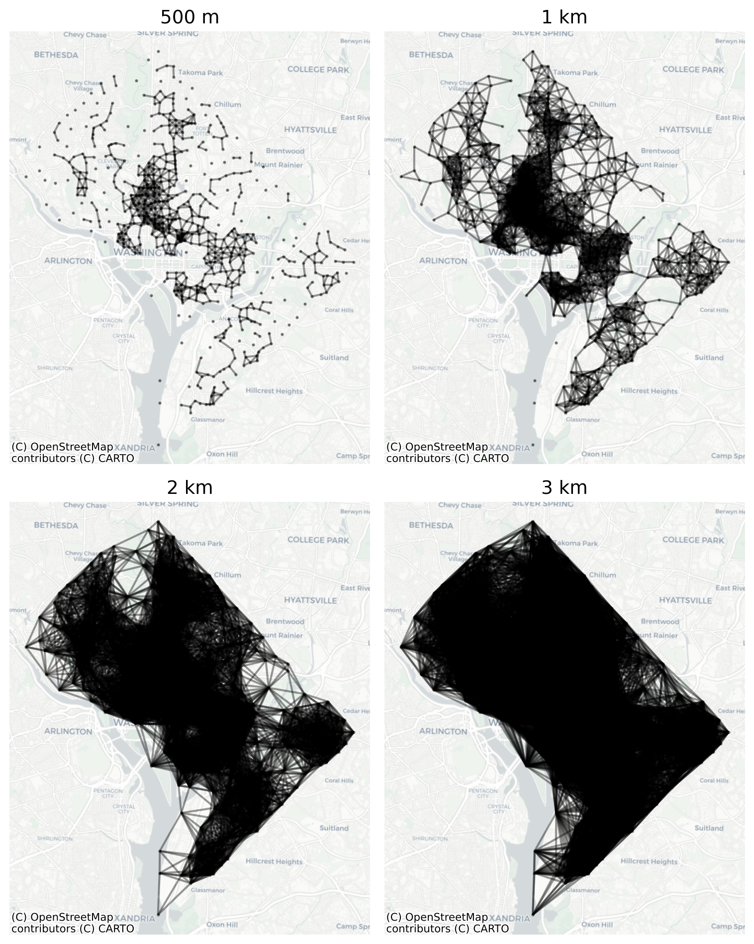
When building a graph based on distance relationships (using polygon data), we need to make a simple assumption: since the distance between two polygons is undefined (is it the distance between the nearest point of each polygon? the furthest points? the average?), we use the polygon centroid as it’s representation. The centroid is the geometric center of each polygon, so it serves as a reasonable approximation for the “average” distance of the poygon. Note that when building a distance band, the threshold argument is measured in units defined by the coordinate reference system (CRS) of the input dataframe. Here, we are using a UTM CRS, which means our units are measured in meters, so these graphs correspond to 1km and 2km thresholds.
Code
dc.crs
<Projected CRS: EPSG:32618>
Name: WGS 84 / UTM zone 18N
Axis Info [cartesian]:
- E[east]: Easting (metre)
- N[north]: Northing (metre)
Area of Use:
- name: Between 78°W and 72°W, northern hemisphere between equator and 84°N, onshore and offshore. Bahamas. Canada - Nunavut; Ontario; Quebec. Colombia. Cuba. Ecuador. Greenland. Haiti. Jamaica. Panama. Turks and Caicos Islands. United States (USA). Venezuela.
- bounds: (-78.0, 0.0, -72.0, 84.0)
Coordinate Operation:
- name: UTM zone 18N
- method: Transverse Mercator
Datum: World Geodetic System 1984 ensemble
- Ellipsoid: WGS 84
- Prime Meridian: Greenwich
Naturally, distance-based relationships are sensitive to the density of observations in space. Since the distance threshold is fixed, denser locations will necessarily have more neighbors, whereas sparse locations may have few or no neighbors (e.g. the three observations in southeast DC in the 1km graph). This can be a useful property of distance-band graphs, because it keeps the notion of ‘neighborhood’ fixed across observations, and in many cases it makes sense for density to increase the neighbor set.
Histograms of Neighbor Cardinalities in Increasing Distances
As the distance band increases, the neighbor distribution becomes more dispersed. In graphs with the smallest bandwidths, there are places in the study region with observations that fail to capture any neighbors (within the 500m and 1km thresholds), which creates disconnections in the graph. The different connected regions of the graph are called components, and it can be useful to know about them for a few reasons.
First, if there is more than one component, it implies that the interaction structure in the study region is segmented. Disconnected components in the graph make it impossible, by definition, for a shock (innovation, message, etc) to traverse the graph from a node in one component to a node in another component. This situation has implications for certain applications such as spatial econometric modeling because certain conditions (like higher-order neighbors) may not exist.
If a study region contains multiple disconnected components, this information can also be used to partition or inspect the dataset. For example, if the region has multiple portions (e.g. Los Angeles and the Channel Islands, or the Hawaiian Islands, or Japan), then the component labels can be used to select groups of observations that belong to each component
Code
g_dist_1000.n_components
5
The one kilometer distance-band graph has 5 components (look back at the map): a large central component, and four lonely observations in the Southern portion along the waterfront, all of which have no neighbors. When an observation has no neighbors, it’s called an isolate.
Since the distance-band is fixed but the density of observations varies across the study area, distance-band weights can result in high variance in the neighbor cardinalities, as described above (e.g. some observations have many neighbors, others have few or none). This can be a nuisance in some applications, but a useful feature in others. Moving back to a graph-theoretic framework, we can look at how certain nodes (census blockgroups) influence others by virtue of their position in the network. That is, some blockgroups are more central or more connected than others, and thus can exert a more influential role in the network as a whole.
Histogram of Degree Centrality in 1km Network Graph
Three graph-theoretic measures of centrality, which capture the concept of connectedness are closness centralty, betweenness centrality, and degree centrality, all of which (and more) can be computed for each node. By converting the graph to a NetworkX object, we can compute these three measures, then plot the most central node in the network of DC blockgroups according to each concept.
Code
# closeness centralityclose = ( pd.Series(nx.closeness_centrality(nxg_dist)).sort_values(ascending=False).index[0])# betweenness centralitybetween = ( pd.Series(nx.betweenness_centrality(nxg_dist)).sort_values(ascending=False).index[0])# degree centralitydegree = pd.Series(nx.degree_centrality(nxg_dist)).sort_values(ascending=False).index[0]# plot the most "central" node according to each metricfocal_kws =dict(marker_kwds=dict(radius=10), style_kwds=dict(fillOpacity=1))centralities =zip(["red", "yellow", "blue"], [close, between, degree])m = g_dist_1000.explore( dc, color="gray", tiles="CartoDB Darkmatter", edge_kws=dict(style_kwds=dict(opacity=0.4)),)for color, measure in centralities: m = g_dist_1000.explore( dc, focal=measure, color=color, focal_kws=focal_kws, m=m, )m
Make this Notebook Trusted to load map: File -> Trust Notebook
Nodes with Maximum Closeness, Betweenness, and Degree Centrality Measures
The map helps clarify the different concepts of centrality. The nodes with the highest closeness and degree centrality are in the densest parts of the graph near downtown DC. The blue subgraph shows the node with the highest degree centrality (i.e. the node with the greatest number of connections within a 1km radius), which is arguably the node with the greatest local connectivity and the red subgraph shows the node with the highest closeness centrality, which is the node with the greatest global connectivity.
The yellow subgraph shows the node with the highest betweenness centrality. Unlike the others, the yellow graph does not have many connections (neighbors) of its own, but instead, it connects three very dense subgraphs and thus serves as a pivotal bridge between these pieces of space. In this case, the blockgroup is literally a polygon that contains several bridges across the Anacostia river, which helps demonstrate the importance of considering infrastructure and the built environment when traversing space–and how much power you wield if, say, you control a bridge for political gain
7.2.2 K-Nearest Neighbors (KNN)
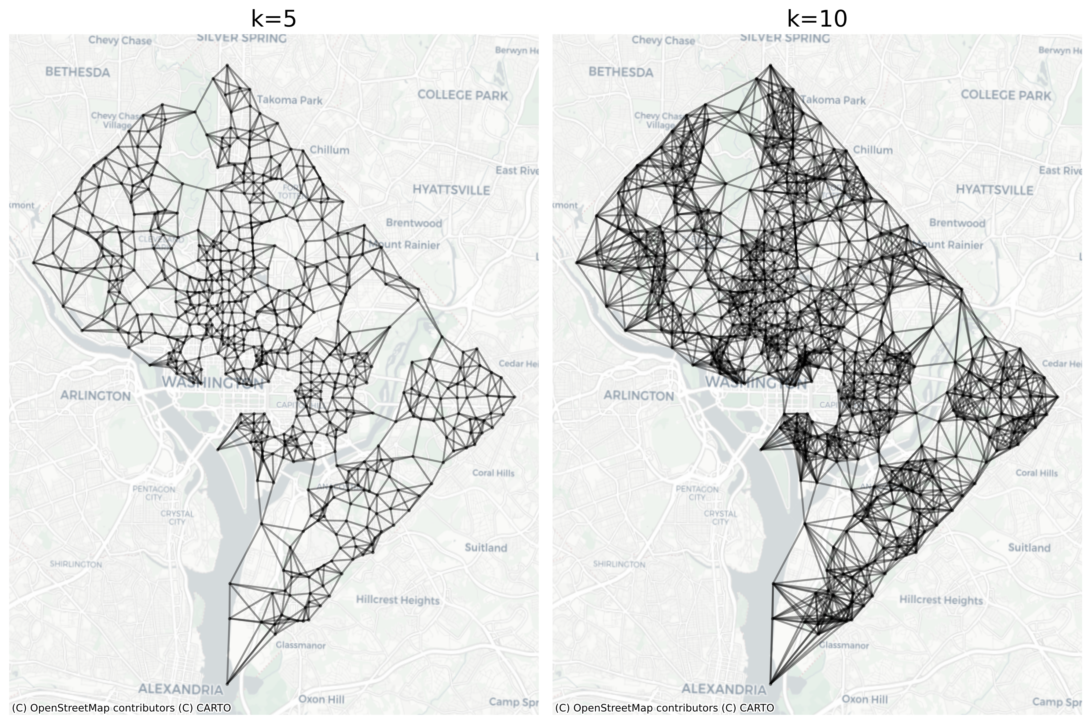
Unlike the distance-band concept of a neighborhood, which defines neighbors according to a proximity criterion, regardless of how many neighbors meet that definition, the K-nearest neighbors (KNN) concept defines the neighbor set according to a minimum criterion, regardless of the distance necessary to travel to meet it. This is more akin to a relative concept of neighborhood, in that both dense and sparse places will have exactly the same number of neighbors, but the distance necessary to travel to interact with each neighbor can adapt to local conditions.
This concept has a different set of benefits relative to the distance-band approach, for example, there is no longer any variation in the neighbor cardinalities (which can be useful, and can ensure a much more connected graph in cases with observations of varying density. But the KNN relationships can also induce asymmetry, which may be a problem in certain spatial econometric applications.
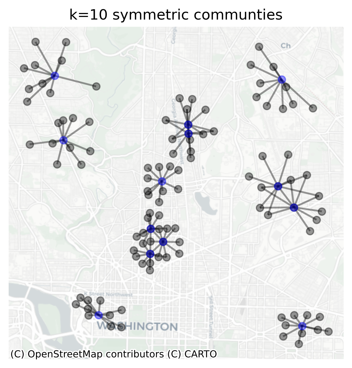
Unlike distance relationships and contiguity relationships nearest-neighbor relationships are often asymmetric. That is, the closest observation to me may have several other neighbors closer than I am (i.e., in this scenario, I am not my neighbor’s neighbor)
In the DC blockgroup data, the vast majority of observations in a KNN-10 graph contain an asymmetric relationship (that’s 98% of the data). Note, this does not mean that 98% of all relationships are asymmetric, only that 98% of the observations have at least one neighbor which does not consider the reciprocal observation a neighbor.
All of the focal nodes plotted here are also neighbors with each of their neighbors (that sounds strange…)
Code
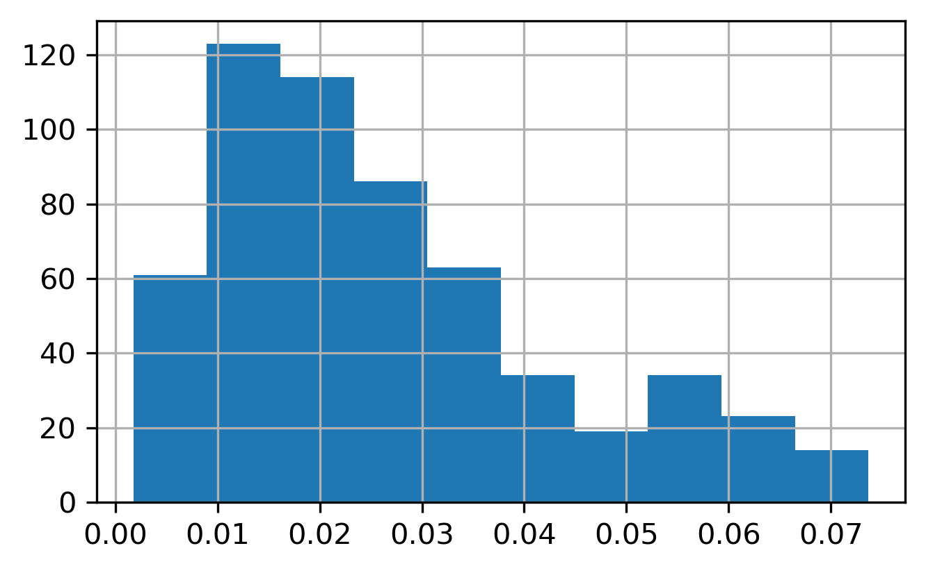
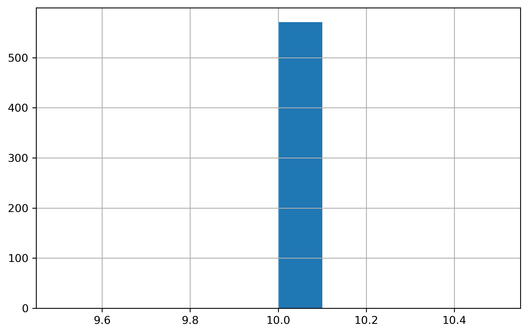
g_knn10.cardinalities.hist()plt.show()
Histogram of KNN-10 Cardinalities
7.2.3 Kernel Functions
In the general cases of the contiguity, distance-band, and KNN graphs, considered so far the relationships between observations are treated as binary: a relationship either exists or does not, and is encoded as a 1 if it exists, and as a 0 otherwise. But they can also all be extended to allow for the relationship to be weighted continuously by some additional measure. For example, a contiguity graph can be weighted by the lengh of the border shared between observations, which would allow observations to have a “stronger” relationship when they have larger sections of common borders.
In the KNN or distance-band cases, it can alternatively make sense to weight the observations according to distance from the focal observation (hence the longstanding terminology for the spatial graph as a spatial weights matrix). Applying a weighting function (often called a distance decay function) in this way helps encode the first law of geography, allowing nearer observations to have a greater influence than further observations. A distance-base weight with a decay function often takes the form of a [kernel](https://en.wikipedia.org/wiki/Kernel_(statistics) weight, where the kernel refers to the shape of the decay function (the commonly-used distance-band weight is actually a just uniform kernel, but sometimes it makes sense to allow variation within the band).
As with the distance-band graph, the kernel graph is only defined for point geometries, so we use the centroid of each polygon as our representation of each unit, and the bandwidth is measured in units of the CRS (so defined as 1km here). Providing different arguments to the kernel parameter changes the weighting function applied at each distance.
The explore method can actually plot the value of the weight for each edge in the graph, although the visualization can be a bit tough to take in. It is easier to visualize one node at a time. Here, the shorter lines will be encoded with lighter colors and longer lines (representing longer distances) are darker as they get assigned lower weights. Note you can re-run the cell below to visualize a different node (or change the focal argument to a particular node instead of a random selection)
Code
g_kernel_linear.explore( dc,# pick a random node in the graph to visualize focal=dc.reset_index().geoid.sample(), edge_kws=dict( column="weight", style_kwds=dict(weight=5), ), tiles="CartoDB Darkmatter",)
Make this Notebook Trusted to load map: File -> Trust Notebook
7.3 Transformations
In many empirical applications of the Graph, it is useful to normalize or standardize the weight structure for each unit (i.e. to rescale the weight value for each unit such that the sum equals 1). In the spatial econometrics literature, this operation is canonically called a transform of the spatial weights matrix. The Graph inherits this terminology; thus, it is extremely common to transform the Graph prior to using it.
Now the weight values for first observation (110010001011) are rescaled to 0.2 for each neighbor (since 110010001011 has 5 neighbors). Note that unlike its the predecessor (the libpysal.weights.Weights class), the Graph is immutable, which means to store the transformation permanently, it is necessary to save it back into a variable!
The Graph class is designed to be flexible, and it can be constructed from a variety of formats. For example, you could create a full pairwise distance matrix from a set of input points and build a graph from that matrix. Here, we will create a new graph based on walk network distances from OpenStreetMap using the pandana library
Code
dc_wgs = dc.to_crs(4326)
Code
dc_walk_net = gio.get_network_from_gdf(dc_wgs)
Generating contraction hierarchies with 16 threads.
Setting CH node vector of size 81596
Setting CH edge vector of size 250726
Range graph removed 253668 edges of 501452
. 10% . 20% . 30% . 40% . 50% . 60% . 70% . 80% . 90% . 100%
Then, we get the nearest node in the OSM network (i.e. the nearest street intersection) and attach it to the nearest centroid of each observation
When using metric="precomputed", the first argument of the builder function is a sparse matrix that encodes relationships between each pair of observations (here, the shortest walking path between each of the observation centroids–provided the path distance is less than 2km)
/var/folders/j8/5bgcw6hs7cqcbbz48d6bsftw0000gp/T/ipykernel_42924/1299152912.py:1: UserWarning: Geometry is in a geographic CRS. Results from 'centroid' are likely incorrect. Use 'GeoSeries.to_crs()' to re-project geometries to a projected CRS before this operation.
g_network = Graph.build_travel_cost(df=dc_wgs.set_geometry(dc_wgs.centroid), network=dc_walk_net, threshold=2000)
/Users/knaaptime/miniforge3/envs/urban_analysis/lib/python3.12/site-packages/libpysal/graph/_utils.py:125: FutureWarning: The behavior of DataFrame concatenation with empty or all-NA entries is deprecated. In a future version, this will no longer exclude empty or all-NA columns when determining the result dtypes. To retain the old behavior, exclude the relevant entries before the concat operation.
adjtable_filled = pd.concat(
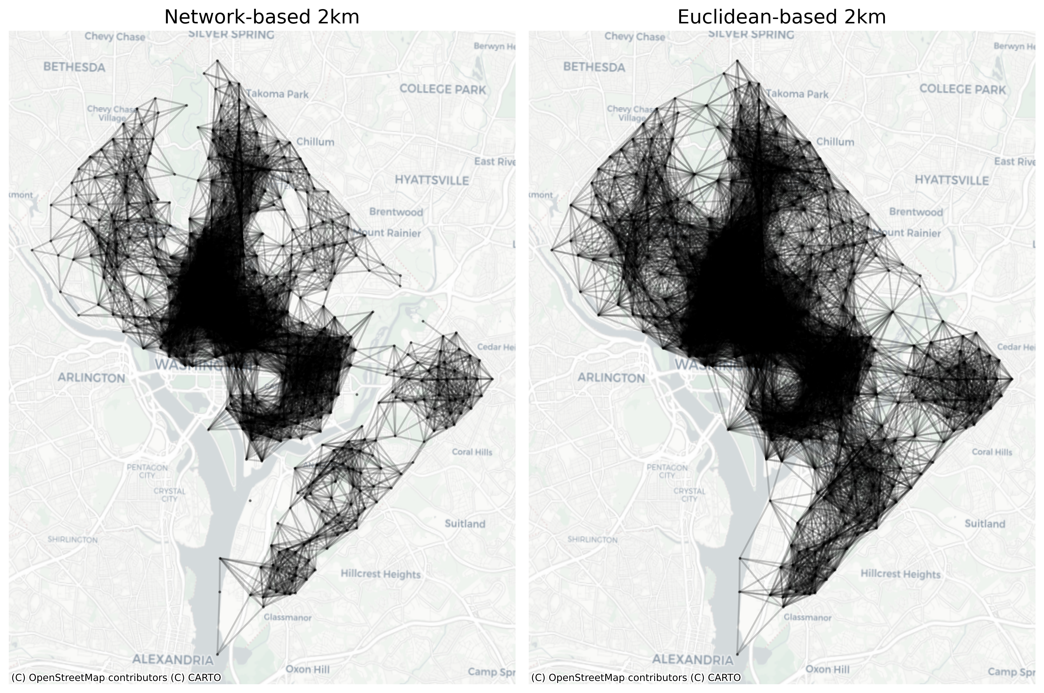
Including the constraint that distance must be measured along the walking network between observations (rather than Euclidean distance) results in some notable distinctions between the two resulting Graphs. In particular, the observations in Northwest DC are no longer connected through rock creek park, and the blockgroups in Southeast are no longer connected across the Anacostia river. This is a more realistic depiction of the potential interaction structure based on infrastructure throughput and helps show how the built environment can be used to develop alternative concepts of spatial connectivity Graphs
Code
g_dist_2000.pct_nonzero
9.264479007241421
Code
g_network.pct_nonzero
6.375578531534377
The graph based on network-constrained 2km distance is more sparse than the graph based on Euclidean distances, showing that transport networks (which are not straight lines) make travel distances further than they sometimes appear. Thus, using them to construct the graph distances results in fewer connections because most observations are further apartwhen measured along the walk network.
7.4.2 Flow-based Graphs
Instead of spatial proximity, the relationship between observations could be represented by other types of flow data, such as trade, transactions, or observed commutes. For example, the Census LODES data contain information on flows between residential locations and job locations at the block level. This uses LODES V7 which is based on 2010 census block definitions
Here, the plot shows flows between origins and destinations. The strong central tendency shows how commutes tend to flow toward the center of the city
7.4.3 Coincident Nodes
Classic spatial graphs are built from polygon data, which are typically exhaustive and planar-enforced. The Census block and blockgroup data we have seen until now are typical in this way; the relationships expressed by polygon contiguity (or distance) are unambiguous and straightforward to model using a simple set of rules, but these spatial representations are often over-simplified or aggregate summaries of real phenomena. Blockgroups, for example, are zones created from aggregated household data, and the relationships can become more complex when working with disaggregate microdata recorded at the household level.
Continuing with the household example, in urban areas, it is common for many observations to be located at the same “place”, for example an apartment building with several units located at the same physical address (in some cases additional information such as floor level could be available, allowing 3D distance computations, but this is an unusually detailed case that also requires the actual floor layout of each building to be realistic…). In these cases, (i.e. with several coincident observations in space) certain graph-building rules like triangulation or k-nearest neighbors can become invalid when the relatioships between points are undefined, yielding, e.g. 10 nearest neighbors at exactly the same location when the user has requested a graph with k=5. How do we choose which 5 among the coincident 10 should be neighbors?
…We dont. Instead, we offer two solutions that make the rule valid:
jitter introduces a small amount of random noise into each location, dispersing a set of coincident points into a small point cloud. This generates a valid topology that can be operated upon using the original construction rule. The tradeoff, here, is that the neighbor-set is stochastic and any two versions of a jittered Graph will likely have very different neighbors.
clique expands the graph internally, as necessary, so that the construction rule applies to each unique location rather than each unique observation. This effectively makes every coincident observation a neighbor with all other coincident observations, then proceeds with the normal construction rule. In other words, we operate on the subset of points for which the original construction rule is valid, then retroactively break the rule to reinsert the omitted observations back into their neighborhoods. In many cases, this can result in a “conceptually accurate” representation of the nighborhood (e.g. where units in the same apartment building are all considered neighbors), however the construction ‘rule’ will ultimately end up broken, which removes some of the desirable properties of certain graphs. For example, a KNN graph with 10 neighbors will now have variation, as some locations will have greater than 10 neighbors.